AARBautomation
Regular price
$125.00 USD
Regular price
Sale price
$125.00 USD
Unit price
per
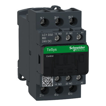
LC1D32BD IEC contactor, TeSys Deca, nonreversing, 32A, 20HP at 480VAC, up to 100kA SCCR, 3 phase, 3 NO, 24VDC coil, open style
LC1D32BD IEC contactor, TeSys Deca, nonreversing, 32A, 20HP at 480VAC, up to 100kA SCCR, 3 phase, 3 NO, 24VDC coil, open style
Couldn't load pickup availability
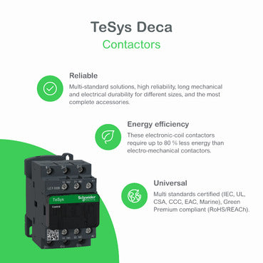
| Range of Product | TeSys Deca |
|---|---|
| Product or Component Type | Contactor |
| Device short name | LC1D |
| Contactor application | Resistive load Motor control |
| Utilisation category | AC-3 AC-1 AC-4 AC-3e |
| Poles description | 3P |
| [Ue] rated operational voltage | Power circuit <= 690 V AC 25...400 Hz Power circuit <= 300 V DC |
| [Ie] rated operational current | 32 A (at <140 °F (60 °C)) at <= 440 V AC AC-3 for power circuit 50 A (at <140 °F (60 °C)) at <= 440 V AC AC-1 for power circuit 32 A (at <140 °F (60 °C)) at <= 440 V AC AC-3e for power circuit |
| [Uc] control circuit voltage | 24 V DC |
| Motor power kW | 7.5 kW at 220...230 V AC 50/60 Hz (AC-3) 15 kW at 380...400 V AC 50/60 Hz (AC-3) 15 kW at 415...440 V AC 50/60 Hz (AC-3) 18.5 kW at 500 V AC 50/60 Hz (AC-3) 18.5 kW at 660...690 V AC 50/60 Hz (AC-3) 7.5 kW at 400 V AC 50/60 Hz (AC-4) 7.5 kW at 220...230 V AC 50/60 Hz (AC-3e) 15 kW at 380...400 V AC 50/60 Hz (AC-3e) 15 kW at 415...440 V AC 50/60 Hz (AC-3e) 18.5 kW at 500 V AC 50/60 Hz (AC-3e) 18.5 kW at 660...690 V AC 50/60 Hz (AC-3e) |
|---|---|
| Maximum Horse Power Rating | 2 hp at 115 V AC 50/60 Hz for 1 phase motors 5 hp at 230/240 V AC 50/60 Hz for 1 phase motors 10 hp at 200/208 V AC 50/60 Hz for 3 phase motors 10 hp at 230/240 V AC 50/60 Hz for 3 phase motors 20 hp at 460/480 V AC 50/60 Hz for 3 phase motors 25 hp at 575/600 V AC 50/60 Hz for 3 phase motors |
| Compatibility code | LC1D |
| Pole contact composition | 3 NO |
| Protective cover | With |
| [Ith] conventional free air thermal current | 10 A (at 140 °F (60 °C)) for signalling circuit 50 A (at 140 °F (60 °C)) for power circuit |
| Irms rated making capacity | 140 A AC for signalling circuit conforming to IEC 60947-5-1 250 A DC for signalling circuit conforming to IEC 60947-5-1 550 A at 440 V for power circuit conforming to IEC 60947 |
| Rated breaking capacity | 550 A at 440 V for power circuit conforming to IEC 60947 |
| [Icw] rated short-time withstand current | 260 A 104 °F (40 °C) - 10 s for power circuit 430 A 104 °F (40 °C) - 1 s for power circuit 60 A 104 °F (40 °C) - 10 min for power circuit 138 A 104 °F (40 °C) - 1 min for power circuit 100 A - 1 s for signalling circuit 120 A - 500 ms for signalling circuit 140 A - 100 ms for signalling circuit |
| Associated fuse rating | 10 A gG for signalling circuit conforming to IEC 60947-5-1 63 A gG at <= 690 V coordination type 1 for power circuit 63 A gG at <= 690 V coordination type 2 for power circuit |
| Average impedance | 2 mOhm - Ith 50 A 50 Hz for power circuit |
| Power dissipation per pole | 2 W AC-3 5 W AC-1 2 W AC-3e |
| [Ui] rated insulation voltage | Power circuit 690 V IEC 60947-4-1 Power circuit 600 V CSA Power circuit 600 V UL Signalling circuit 690 V IEC 60947-1 Signalling circuit 600 V CSA Signalling circuit 600 V UL |
| Overvoltage category | III |
| pollution degree | 3 |
| [Uimp] rated impulse withstand voltage | 6 kV IEC 60947 |
| Safety reliability level | B10d = 1369863 cycles contactor with nominal load EN/ISO 13849-1 B10d = 20000000 cycles contactor with mechanical load EN/ISO 13849-1 |
| Mechanical durability | 30 Mcycles |
| Electrical durability | 1.65 Mcycles 32 A AC-3 <= 440 V 1.4 Mcycles 50 A AC-1 <= 440 V 1.65 Mcycles 32 A AC-3e <= 440 V |
| Control circuit type | DC standard |
| Coil technology | Built-in bidirectional peak limiting diode suppressor |
| Control circuit voltage limits | 0.1...0.25 Uc (-40…158 °F (-40…70 °C)):drop-out DC 0.7...1.25 Uc (-40…140 °F (-40…60 °C)):operational DC 1...1.25 Uc (140…158 °F (60…70 °C)):operational DC |
| Inrush power in W | 5.4 W 68 °F (20 °C)) |
| Hold-in power consumption in W | 5.4 W 68 °F (20 °C) |
| Operating time | 63 ±15 % ms closing 20 ±20 % ms opening |
| Time constant | 28 ms |
| Maximum operating rate | 3600 cyc/h at 60 °C |
| Connections - terminals | Control circuit: screw clamp terminals 1 0.002…0.006 in² (1…4 mm²) - cable stiffness: flexible without cable end Control circuit: screw clamp terminals 2 0.002…0.006 in² (1…4 mm²) - cable stiffness: flexible without cable end Control circuit: screw clamp terminals 1 0.002…0.006 in² (1…4 mm²) - cable stiffness: flexible with cable end Control circuit: screw clamp terminals 2 0.002…0.004 in² (1…2.5 mm²) - cable stiffness: flexible with cable end Control circuit: screw clamp terminals 1 0.002…0.006 in² (1…4 mm²) - cable stiffness: solid without cable end Control circuit: screw clamp terminals 2 0.002…0.006 in² (1…4 mm²) - cable stiffness: solid without cable end Power circuit: screw clamp terminals 1 0.004…0.02 in² (2.5…10 mm²) - cable stiffness: flexible without cable end Power circuit: screw clamp terminals 2 0.004…0.02 in² (2.5…10 mm²) - cable stiffness: flexible without cable end Power circuit: screw clamp terminals 1 0.002…0.02 in² (1…10 mm²) - cable stiffness: flexible with cable end Power circuit: screw clamp terminals 2 0.002…0.009 in² (1.5…6 mm²) - cable stiffness: flexible with cable end Power circuit: screw clamp terminals 1 0.002…0.02 in² (1.5…10 mm²) - cable stiffness: solid without cable end Power circuit: screw clamp terminals 2 0.004…0.02 in² (2.5…10 mm²) - cable stiffness: solid without cable end |
| Tightening torque | Control circuit 15.05 lbf.in (1.7 N.m) screw clamp terminals flat Ø 6 mm Control circuit 15.05 lbf.in (1.7 N.m) screw clamp terminals Philips No 2 Power circuit 22.1 lbf.in (2.5 N.m) screw clamp terminals flat Ø 6 mm Power circuit 22.1 lbf.in (2.5 N.m) screw clamp terminals Philips No 2 Control circuit 15.05 lbf.in (1.7 N.m) screw clamp terminals pozidriv No 2 Power circuit 22.1 lbf.in (2.5 N.m) screw clamp terminals pozidriv No 2 |
| Auxiliary contact composition | 1 NO + 1 NC |
| Auxiliary contacts type | Mechanically linked 1 NO + 1 NC IEC 60947-5-1 Mirror contact 1 NC IEC 60947-4-1 |
| Signalling circuit frequency | 25...400 Hz |
| Minimum switching voltage | 17 V for signalling circuit |
| Minimum switching current | 5 mA for signalling circuit |
| Insulation resistance | > 10 MOhm for signalling circuit |
| Non-overlap time | 1.5 ms on de-energisation between NC and NO contact 1.5 ms on energisation between NC and NO contact |
| Mounting Support | Rail Plate |
| Standards | CSA C22.2 No 14 EN 60947-4-1 EN 60947-5-1 IEC 60947-4-1 IEC 60947-5-1 UL 60947-4-1 IEC 60335-1:Clause 30.2 IEC 60335-2-40:Annex JJ UL 60335-2-40:Annex JJ CSA C22.2 No 60947-4-1 |
|---|---|
| Product Certifications | UL CCC CSA Marine UKCA EAC CB Scheme |
| IP degree of protection | IP20 front face IEC 60529 |
| Protective treatment | THIEC 60068-2-30 |
| Climatic withstand | IACS E10 exposure to damp heat IEC 60947-1 Annex Q category D exposure to damp heat |
| Permissible ambient air temperature around the device | -40…140 °F (-40…60 °C) 140…158 °F (60…70 °C) with derating |
| Operating altitude | 0...9842.52 ft (0...3000 m) |
| Fire resistance | 1562 °F (850 °C) IEC 60695-2-1 |
| Flame retardance | V1 conforming to UL 94 |
| Mechanical robustness | Vibrations contactor open 2 Gn, 5...300 Hz) Vibrations contactor closed 4 Gn, 5...300 Hz) Shocks contactor closed 15 Gn for 11 ms) Shocks contactor open 8 Gn for 11 ms) |
| Height | 3.3 in (85 mm) |
| Width | 1.8 in (45 mm) |
| Depth | 4.0 in (101 mm) |
| Net Weight | 1.179 lb(US) (0.535 kg) |
| Category | US10I1222355 |
|---|---|
| Discount Schedule | 0I12 |
| GTIN | 3389110357257 |
| Returnability | Yes |
| Country of origin | SG |
| Unit Type of Package 1 | PCE |
|---|---|
| Number of Units in Package 1 | 1 |
| Package 1 Height | 1.97 in (5.000 cm) |
| Package 1 Width | 3.62 in (9.200 cm) |
| Package 1 Length | 4.41 in (11.200 cm) |
| Package 1 Weight | 20.635 oz (585.000 g) |
| Unit Type of Package 2 | S02 |
| Number of Units in Package 2 | 15 |
| Package 2 Height | 5.91 in (15.000 cm) |
| Package 2 Width | 11.81 in (30.000 cm) |
| Package 2 Length | 15.75 in (40.000 cm) |
| Package 2 Weight | 19.963 lb(US) (9.055 kg) |
| Unit Type of Package 3 | P06 |
| Number of Units in Package 3 | 240 |
| Package 3 Height | 29.53 in (75.000 cm) |
| Package 3 Width | 23.62 in (60.000 cm) |
| Package 3 Length | 31.50 in (80.000 cm) |
| Package 3 Weight | 340.614 lb(US) (154.500 kg) |
| Warranty | 18 months |
|---|